| з”Ё MatWeb зҷ»е№ҝе‘Ҡ! | ||
| и¶ҠиҝҮ59,000 д»ҘдёҠ, йҮ‘еұһгҖҒеЎ‘ж–ҷгҖҒйҷ¶з“·е’ҢеҗҲжҲҗзү©зҡ„ж•°жҚ®иө„ж–ҷеә“гҖӮ | ||
|
дё»йЎө • жҗңеҜ» • е·Ҙе…· • дҫӣеә”е•Ҷ • ж–Ү件еӨ№ • жңүе…іжҲ‘们 • еёёз”Ёй—®йўҳ • зҷ»еҪ• • |
||
| | | | | | |
|
||||
Unique Capabilities of Pressure Infiltrated Castingҷ
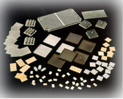
Introduction Pressure Infiltrated Casting (PICҷ) has come a long way in recent years. It has proven to be up to the challenges of delivering products with tight tolerances, high thermal conductivity, tailored coefficient of expansion, reduced weight and high stiffness. Current core capabilities are schematically illustrated in Figure 1. They include net-shape metal reinforced components, mainly AlSiC (silicon carbide aluminum). Other materials, such as graphite reinforced aluminum and diamond reinforced aluminum, used in applications where very high heat dissipation is required, have recently been developed.
Net Shape Casting Net-shape thin plate casting ability is one of the fundamental advantages of the PICҷ manufacturing process. AlSiC Base plates 0.010”-0.2” thick and as large as 11”x7” have been in production. Net-shape parts are produced by infiltrating preforms which contain all the details of the finished part within a casting mold system. The casting molds are designed not only to contain the preforms, but to form the desired thickness of aluminum skin and all the dimensions of the final part. As-cast parts can easily meet +/- 0.003” in length and width. Figure 2 shows an example of a DBA (Direct Bond Aluminum)- AlSiC hyrbrid structure with an integrated heat sink, carrier baseplate, ceramic substrate, and circuit pattern. The part has void-free in situ bonds, created during a single pressure infiltrated casting operation.
Plating and Coating Metal skin on the finished product is characteristic of the PICҷ process. The pure metal skin allows the part to be plated or finished as though it were an aluminum metal part. Cast parts fabricated using the PICҷ process can be plated using traditional aluminum plating techniques and coated with various specialized coatings. Ni and Ni/Au plating are utilized when AlSiC parts are soldered to other electronic components. Cu base thermal spray coatings are also suitable for specific solder alloys. Chemical film coatings are suitable for epoxy bonding. Since the coatings cost less than the Ni plating, these coatings easily replace Ni plating in applications where the parts will be exposed to mildly corrosive environments. Skinless parts can also be produced with PICҷ. In Situ Bonding Another advantage of the PICҷ process is the ability to bond a variety of formerly unbondable materials. Titanium, iron-based alloys, and ceramics have all been joined to AlSiC in situ using the PIC process. Figure 3 shows a hermetically sealed AlSiC electronic package with a Ti seal ring that was bonded in situ during the PICҷ process. An optical micrograph from a polished section of an in-situ formed AlSiC/Ti seal ring interface and welded Ti lid/Ti seal ring interface are shown in Figure 3. The aluminum alloy in the joint is similar in chemical composition to the AlSiC matrix and the aluminum skin covering the composite. There is no discontinuity such as cracks or porosity at the aluminum/AlSiC interface and the aluminum/Ti interface.
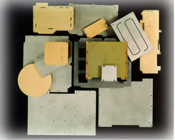
Due to the matched CTE of AlSiC and titanium, a Ti seal ring can be joined to AlSiC composites with minimal post-fabrication stress. A Ti lid can then be welded to the Ti seal ring utilizing laser welding. Due to the high thermal conductivity of AlSiC, the interface temperature remains below the melting temperature of aluminum alloy during laser welding process. As a result, there is no change expected in this interface during the welding process. Laser sealed AlSiC packages produced with Ti seal rings maintain the hermetic integrity after 1,100 thermal cycles between -55 and 125әC. Design Possibilities The variety of products in Figure 4 show the design flexibility provided by the PICҷ process. Table 1 provides some general guidelines for engineers and designers. Pressure-Infiltrated Casting by PCC-AFT Composites gives engineers the freedom to explore new opportunities in the design of thermal management solutions.
Table 1: PCC/AFT Composites General Casting Design Guidelines
Table 2: Properties of materials produced by PCC-AFT Composites Group’s Pressure Infiltrated Casting process.
|
|||||||||||||||||||||||||||||||||||||||||||||||||||||||||||||||||||||||||||||||||||||||||||||||||||||||||||||||||||||||||||||||
|
и®ўйҳ…зү№зә§жңҚеҠЎ й«ҳзә§е…Ҳиҝӣ • жһ„жҲҗд»Ҫ • зү№жҖ§ • жқҗж–ҷзұ»еһӢ • еҲ¶йҖ е•Ҷ • е•Ҷж Ү • UNSеҸ·з Ғ е№ҝе‘Ҡ • йҖ’дәӨиө„ж–ҷ • иө„ж–ҷеә“и®ёеҸҜиҜҒ • зҪ‘еқҖи®ҫи®Ўз®ЎзҗҶ • дәӨжҳ“еҸ‘иЎҢ дҫӣеә”е•ҶеҗҚеҚ• • еҚ•дҪҚиҪ¬еҸҳ • еҸӮиҖғ • ж–°ж¶ҲжҒҜ • й“ҫжҺҘз«ҷ • еҚҸеҠ© • йҖҡи®Ҝ • зҪ‘еқҖеӣҫзӨә • еёёз”Ёй—®йўҳ • дё»йЎө |
||
| иҜ·иҜ»е…ідәҺжқҗж–ҷж•°жҚ®зҡ„дҪҝз”Ёи®ёеҸҜеҚҸи®®е’ҢжҲ‘们зҡ„йҡҗз§ҒжқғгҖӮиҜўй—®жҲ–иҜ„и®әжңүе…і MatWeb? иҜ·дёҺwebmaster@matweb.com иҒ”зі»гҖӮжҲ‘们ж„ҹи°ўжӮЁеҜ№ MatWebзҡ„еҸӮдёҺгҖӮ
жң¬з«ҷзӮ№з”ұ Automation Creations, Inc. и®ҫи®Ўе’Ңз»ҙжҠӨгҖӮиҝҷдёӘзҪ‘з«ҷзҡ„еҶ…е®№, MatWeb зҡ„е•Ҷж Ү,дёҺ "MatWeb" з”ұ Automation Creations, Inc.зүҲжқғ1996-2006жӢҘжңү гҖӮ MatWeb ж„Ҹж¬ІдёәдёӘдәәдҪҝз”Ё , йқһе•Ҷдёҡз”ЁйҖ”гҖӮиҝҷдёӘз«ҷзӮ№зҡ„еҶ…е®№гҖҒз»“жһңе’ҢжҠҖжңҜж•°жҚ®,жңӘз»Ҹз”ұ Automation Creations, Inc. е…Ғи®ё, дёҚеҸҜд»Ҙиў«з”өеӯҗ,ж‘„еҪұжҲ–е®һиҙЁдёҠең°еҶҚз”ҹдә§жҲ–иҮӘеҠЁеҢ–еҲӣдҪңгҖӮ |
||